Submit Button
Press the submit button after the above data has been entered and this will return an arcing
current Iarc and a reduced arcing current Iarc_min providing there are no invalid entries.
Iarc Disconnection Time
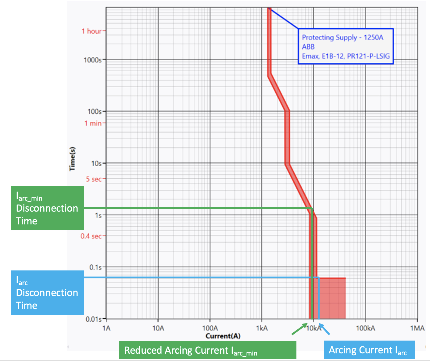
A value of time in seconds needs to be entered for the corresponding Arcing Current (Iarc). This will be
from the upstream protection device time current curve. As shown below.
Iarc_min Disconnection Time
A value of time in seconds needs to be entered for the corresponding reduced arcing current (Iarc_min).
This will be from the upstream protection device time current curve. As shown in Figure 14.5 below.

Figure 14.5 Arcing Current Variations
The example in Figure 14.5 is for a typical low voltage air circuit breaker and as can be seen the arcing current in this case is 12.2 kA (marked in blue) with a corresponding Iarc disconnection time is 0.06 seconds. The reduced arcing current Iarc_min is 9.9 kA (marked in green) with a corresponding Iarc_min disconnection time of 1.2 seconds.
Add Motor Contribution
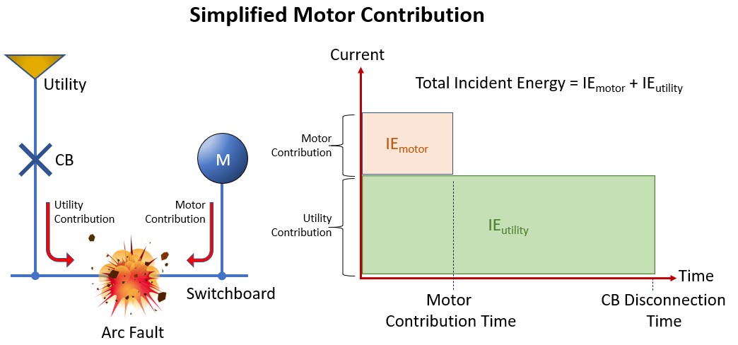
This is a tick box if you wish to add motor contribution. If there is significant contribution from induction
motors, this will have the effect of increasing the prospective short circuit current for a finite time and
therefore increasing the incident energy level. As can be seen in the diagram Figure 14.6 below, an
amount of incident energy from the motor, which is represented by the pink box, is added to the
calculated incident energy contribution from the utility.

Figure 14.6 Motor Contribution
By ticking the Add Motor Contribution box, a separate control panel will be shown with the following fields.
Induction Motors Total Full Load Current
This field asks for the induction motor full load current in amperes which can be either a single or
grouped motor load in amperes.
Motor Fault Contribution * FLA
This field is motor fault contribution times full load current which is an engineering judgement. A motor
contribution of between four- and six-times full load current is usually acceptable.
Contribution Time in Seconds.
The final field is a drop-down field for the motor contribution time in seconds. Again, this is to be based
upon engineering judgement, but induction motor contribution typically lasts from one to four cycles
(0.02 to 0.08 seconds at 50Hz) and synchronous motors, this can last from six to eight cycles (0.12 to
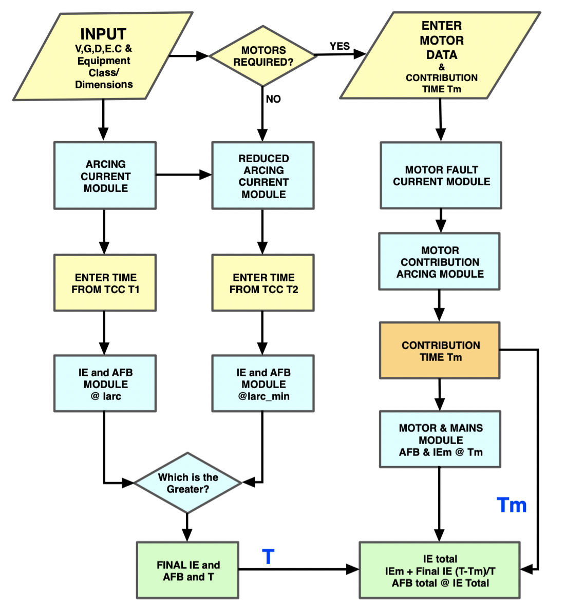
0.16 seconds). In summary, the IEEE 1584 – 2018 Calculator follows the logic in the flowchart given in
Figure 14.7.
For the sake of simplicity, the calculator shows motors connected downstream of the fault meaning that the sum of utility fault current plus motor fault current will be applied for whatever time that is entered into the motor contribution time field. This may give a slightly higher incident energy in cases where the protective device operates quicker than the motor contribution time. Motors that are connected upstream of the protective device need to be factored into the mains contribution which is derived from a separate fault level study as this may impact on the protective device operating time.

Figure 14.7 Calculations flowchart